Video capture board
This type of data source is used when you want to receive the video flow from analog cameras.
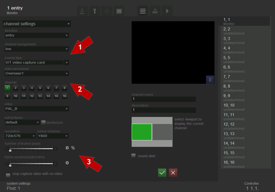
In order to select and configure the video capture card as a data source it is necessary to perform the following steps consistently (see fig. Channel settings. Capture board adjustment):
- select source type - video capture card;
- select a video flow processor and a channel;
- configure the video flow transmission parameters.
When the video capture card is selected as a video source, video transmission parameters can be set for it.
Capture card – allows to select a video flow processor (Overseer1, Overseer2, Overseer3, Overseer4). Each of these processors handles up to 50 half-frames (board handles up to 200 half-frames). In case when the system processes from 2 to 4 recognition channels, if it is possible, channels are distributed by one for each processor.
Attention!
If one processor is required to recognize numbers of vehicles from more than one camera, the characteristics of the input video flow (resolution, color) should be identical.
Channel. Every Overseer card has 16 channels for connecting cameras. Channel corresponds to a number on the connector of the camera adapter (DB25-16BNC), to which the camera is connected.
Video. Overseer supports two video flow transmission standards: PAL_B and NTSC_M. Video format and resolution settings should be adjusted according to the video source and required image in the channel.
Half-frames. Default settings for half-frames are recommended; change it, only if the image "tears" by 1-2 pixels.
The selection of the option "deinterlace" applies the filter required to eliminate the effect of interlacing to the selected video. . In the case of interlacing, which arises when combining the previous half-frame with the current one (eg the even lines- from the current half-frame and odd- from the previous one) in the video of interlaced format, the edges of lenses have the form of comb (see fig. Channel settings. Frame with interlacing) which significantly affects the recognition quality.
Resolution. This field is for choosing necessary resolution. Raising resolution in direct ratio affects quality of recognition and inversely affects the velocity of the data transmission.
Color space. For black and white images it is recommended to use a color space Y800; for color images — UYUY.
The number of broken pixels, % - defines % of broken pixels, and the increase of which brings to the discard frame. “Broken" are pixels ("pixels" - it is the code name in this case, in fact it is the bytes), which were transferred at a time when the internal buffer was full. In the picture at this time, there is the string that contains the image of the previous frame. For each GPU has a counter of "broken" bytes. After the successful capturing, the counter value is read, and if the settings are discarded, depending on the value of the counter, half-frame can be discarded. With regular overflows it can improve the image quality due to the number of frames per second.
The time of the frame synchronization – when multiplexing of different camcorders, video processor has no time to reinitialize, then occurs the vertical synchronization and the capture begins with any half-frame row. To avoid this situation, one can set the number of rows to skip before the image capture, then one or more half-frames are being skipped and the video processor has time to synchronize with the image.
Stop capture video without video signal - when placing this flag the video capture without video signal is stopped. This reduces the load on the system and multiplexing can increase the number of frames per second in the other filters, in which video source is present.
