Guide for selection, installation and setting of video surveillance cameras
Camera and Lens Requirements
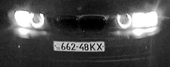
For recognition systems number plates should fulfill the following requirements:
- according to the Vienna Convention number plate should be formed in such way so it can be recognized under good weather conditions from distance not less than 40 m (130 feet) while placed on the axis of the not moving vehicle;
- according to the Russian Government Standard 50577-93 number plate should be placed in such way so it can be recognized in the dark from distance not less than 20 m while lighted with vehicle’s standard lighting.
For recognition it is necessary to make sure that frames with number plates fulfill the following characteristics:
- number plate should be fully placed in the frame;
- height of the symbols: not less than 15px, width: not less than 2px;
- symbols should be sharp, not smeared, undistorted, not overexposed, evenly lighted;
- symbols should be visually differentiated;
- technical requirements for the number plates should follow according government standards;
- minimum allowed contrast with evenly dirty number plate should not be less than 10% (contrast differentiation of symbols to the background is 25 on 256 point scale);
- maximum allowed uneven dirtiness is not more than 12% (ratio of the dirty area of the number plate to its whole area);
- geometrical proportions of the number plate picture should not differ from such proportions of the number plate itself with more than 10%.
- without the effect of interlacing (on speed)*.
* for analog cameras
It is necessary to fulfill the requirements for video cameras listed in the Table 1. (Video camera requirements)
| # | Characteristic | Range of values | Comment |
|---|---|---|---|
| 1 | Camera type |
|
List of recommended cameras can be found in the “Recommended Equipment” section |
| 2 | Resolution of video surveillance camera | From 520 TV lines horizontally. | It is necessary to use high resolution cameras. Only in such case percentage of correct recognition that is stated in the system characteristics is guaranteed. |
| 3 | Lighting in the control zone |
|
In the dark 50 lux are provided by the standard lighting of the roads for vehicles. |
| 4 | Automatic gain control | LOW or MIDDLE depending on camera. | This function should be turned on. Turning on automatic gain control increases not only video signal, but all noise from matrix as well. The value is set individually for each camera. |
| 5 | Auto diaphragm and auto electronic shutter |
|
Image should be sharp. Sharpness is reached by fixed shutter speed of lens’s electronic shutter. Setting of the shutter to the fixed position is the most important parameter. With high exposure, i.e. low shutter speed (1/100, 1/50 sec) images of moving objects appear blurred. If the declivity angle of roll of the camera relatively to the registration number exceeds 10°, it is recommended to reduce the shutter speed half as much for the increasing of picture sharpness. |
| 6 | Camera chromaticity | Black and white | It is recommended to use black and white cameras unless it is necessary to store color pictures of the vehicle. This is because color cameras while having same characteristics have less sensitivity and pictures appear less sharp. |
Camera Installation
Allowed range of distortion is provided by conditions of shooting:
- the angle of vertical inclination of the camera is not more than 40° (declination of the camera to the horizon);
- horizontal deflection angle is up to 30° (deviation of the optical axis of the camera from motion vector of the mainstream vehicles);
- declivity angle of roll of the registration number relatively to the road does not exceed 10° (both clockwise and counter clockwise).
If the above parameters are exceeded, recognition will be carried out with decrease of quality.
The main installation parameters for video cameras are presented in the table Camera installation parameters.
| Name of the parameter | Maximum allowed value | Recommended (optimal) value |
|---|---|---|
| Height of the camera’s placement | 20 meters | 6 meters |
| Camera’s vertical incline | 30 º | 18 º |
| Camera’ s horizontal incline | 20 º | 5-10 º |
| Declivity angle of roll of the registration number relatively to the road | 10 º | 10 º |
Table Control zone parameters shows the main parameters of control zones for different types of cameras that were installed according to the recommendations. When calculating the length of zones, length of the number plate is taken as 520mm or 80-140 in pixels.
| Camera resolution, px | Visible area, м | Visible area, lanes (width of lane 2,5 м) | Visible area, lanes (width of lane 4 м) |
|---|---|---|---|
| 720*288 | 1,87 – 2,67 | 1 - 1,5 | 0,5 - 1 |
| 800*600 | 2,97 -5,2 | 1 - 2 | 0,5 - 1,5 |
| 1280*960 | 4,75 - 8,32 | 2 - 3,5 | 1 - 1,5 |
| 1920*1080 | 7,13 -12,48 | 3 - 5 | 2 - 3 |
| 2048*1536 | 7,60 -13,31 | 3 - 5,5 | 2 - 3,5 |
| 2560*1600 | 9,50-16,64 | 3,5 - 6,5 | 2,5 - 4 |
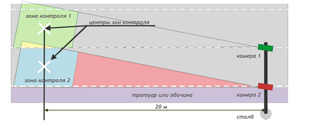
Standard placement of cameras above roads is 6 meters above the center of the controlled lane. This places center of the control zone 20 meters from mounted video camera.
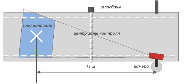
Standard placement for control of entrances and exits to the territory is 3 meters above the edge of the lane. This places center of the control zone 11 meters from the camera on the center of the lane.
Camera Setting
Exposure
Exposure is the time interval during which the shutter holds the camera lens open. Modern cameras have the exposure range 1/50 - 1/500 000 sec. This parameter is adjusted manually or selected automatically. The lower the shutter speed the longer the exposure and the lighter the pictures. But as the result of the increasing of each frame shooting time the registration numbers of the vehicles moving with high speed may be found blurred.
Cameras which don’t allow assigning the shutter speed rate manually cannot be used in the recognition system.
The low shutter speed brings about the smearing effect on the pictures when the registration number seems clear visible on the video. But using the stop-motion view it can be observed that the registration number is blurred.
To escape the effects shown on the picture it is necessary to disable the automatic shutter speed adjustment and assign it manually in following way:
- If the vehicle speed is less than 40 km/h - the shutter speed must be no more than 1/500 sec;
- If the vehicle speed is more than 40 km/h and reaches 150 km/h than the shutter speed must be no more than 1/1000 sec.*
* If the declivity angle of roll of the camera relatively to the registration number exceeds 10°, it is recommended to reduce the shutter speed half as much for the increasing of picture sharpness.
Camera Sharpness
To provide the correct registration number recognition the number must be sharp (fine) in a whole frame. The diaphragm settings and the depth of field should be taken into account during the sharpness adjustment. More detailed review of this parameter can be received from the supplier of lens for your cameras or from the camera manual. If the sharpness is low, the image will be fine only in the point of focus and fuzzy on the edges. Over the time of passing the vehicle control zone the camera will make several (3-5) photos.
If on the most of the frames the image is fuzzy, but on the one (in the center of control zone) the image is fine, the SDK may recognize the number incorrectly basing on the ‘fuzzy’ majority of frames.
The sharpness is regulated by the adjustment of the diaphragm. The more the diaphragm is open, the less is the depth of the field and the more light hits an array (the image will be lighter).
The lenses with auto diaphragm have two settings - Level and Auto Light Control, ALC. The mean value of the diaphragm is manually assigned using the first of the settings; the second one controls the brightness changes sensitivity of the diaphragm automatic control circuit. Usually this adjustment is set at middle position because the excessively fast response of the automatic control circuit may cause its self-excitation under the minimal brightness changes and as a result the lens diaphragm will intermittently spontaneously open and close.
To adjust the camera it is necessary to direct it so that the maximal light quantity hit camera lens. CAREFULLY it is forbidden to direct the camera at the sun; this may cause the breakdown of the camera array. Reduce the Level until the diaphragm is not closed and then you will see that the image is black. Then swell the Level until the image appears. Then close the camera lens for 5 seconds. Make sure that the image occurs when the lens is open. If the image doesn`t appear, repeat the adjustment.
Video Signal Amplification
The adjustment is performed under the bad light conditions. The aim of the adjustment is to choose such gain coefficient under which the useful video signal amplification doesn’t result in its noise pollution.
“Good” and “Bad” Number Plates
Before starting the recognition, make sure that the camera is set up properly and frames contain number plates that fulfill the recruitments stated in the “Camera and Lens Requirements” section.
Weather condition (rain, snow) make up natural distortion of the picture. This negatively affects recognition percentage as well. Increasing of the number’s size in the frame will help to reduce this negative impact.
Be careful with what number templates are supported by your recognition module. Moreover, be attentive to what templates are selected in the configuration (only main types are selected by default).
Examples of “bad” number templates can be found in the table below.
Examples of “good” numbers number templates can be found below.
Recommended Equipment
We recommend using the following equipment for video surveillance systems with vehicle recognition function:
Analog cameras
- Acumen AI-CC91 *
- Acumen AI-CC93 *
- Balter BM-KA61
- Baxal ICE-CM2XUTP
- Baxal ICE-B2XHTP
- Bosch REG-L1 *
- Bosch LTC-0385
- Bosch LTC 0485
- Bosch LTC 0495
- Bosch LTC 0498
- Bosch LTC 0620
- Infinity CX-TWDN560SD *
- Infinity MX-580SD *
- Infinity QX-580S *
- Infinity SR-TDN530SD *
- Komoto AVN-320L6~60
- Komoto AVP-320L6~60
- Komoto AVN-240L6~60
- Komoto AVP-240L6~60
- Komoto PVN-80L16
- Komoto PVP-80L16
- Komoto PVN-80RL12
- Komoto PVP-80RL12
- Komoto PVN-80RL16
- Komoto PVP-80RL16
- Komoto PVN-80RL25
- Komoto AVN-240ZL22
- Komoto AVP-240ZL22
- Komoto AVN-320ZL22
- Komoto AVP-320ZL22
- Komoto AVN-240ZL10
- Komoto AVP-240ZL10
- Komoto MVN-80RL
- Komoto PVN-80RL
- Komoto AVN-80RL
- Komoto MVP-80RL
- Komoto PVP-80RL
- Komoto AVP-80RL
- Komoto KMT-7780 CNI-T/CPI-T
- Komoto KMT-1658 HN-TB/ HP-TB
- Komoto KMT-1779N
- Komoto KMT-1779P
- Komoto KMT-1767HN
- Komoto KMT-1767HP
- Komoto KMT-1796HIN
- Komoto KMT-1796HIP
- Komoto KMT-1797HIN
- Komoto KMT-1797HIP
- Komoto KMT-1799HIN
- Komoto KMT-1799HIP
- Komoto KMT-7785HN
- Komoto KMT-7785HP
- Komoto NVB-1200T
- Komoto NVB-1200
- Komoto NVB-960T
- Komoto NVB-960
- Komoto NVB-600T
- Komoto NVB-600
- Lilin CMP176P
- Samsung SCC-B2335P
- SPTT ТКН259
- Watec WAT-902H2 Supreme
- Watec WAT-902H3 Supreme
- Watec WAT-902H2 Ultimate
- Watec WAT-902H3 Ultimate
IP cameras
- Arecont Vision AV1115-DN
- Arecont Vision AV1305-DN
- Arecont Vision AV1310-DN
- Arecont Vision AV1300-DN
- Arecont Vision AV2105-DN
- Arecont Vision AV2110-DN
- Arecont Vision AV2115-DN
- Arecont Vision AV3100-DN
- Arecont Vision AV3105-DN
- Arecont Vision AV3115-DN
- Arecont Vision AV1125-IR
- Arecont Vision AV1325-IR
- Arecont Vision AV2125-IR
- Arecont Vision AV3125-IR
- Axis 221
- Axis Р1343
- Axis P1344
- Axis P1346
- Basler BIP2-640c dn
- Basler BIP2-1000c dn
- Mobotix MX-M12D-Sec-DNight-D43N135
- Mobotix MX-M12D-Sec-DNight-D22N22
- Mobotix MX-M12D-Sec-DNight-D22N43
- Mobotix MX-M12D-Sec-DNight-D22N135
- Mobotix MX-M12D-Sec-DNight-D43N43
- Mobotix MX-M12D-Sec-DNight-D43N22
- Mobotix MX-M12D-Sec-DNight-D135N135
- Mobotix MX-M12D-Sec-DNight-D135N22
- Mobotix MX-M12D-Sec-DNight-D135N43
- Panasonic SP-WV306
* can be used only with Parking type systems
IR projectors
- Komoto KMT-7797
- Komoto KMT-7795
- Komoto NV-960
- Komoto NV-960F
- Komoto MV-1080
- Komoto MV-960
- Komoto MV-640
- Komoto MV-540
- Komoto MV-400
- Komoto MV-320
- Komoto KMT-7799S
- Komoto KMT-6081B
- Komoto KMT-6082B
- Komoto KMT-6083B
- Komoto KMT-6081C
- Komoto KMT-6082C
- Komoto KMT-6083C
- Komoto KMT-1200W
- Komoto A913
- Komoto NV-320
- Komoto NV-600V
- Komoto AV-320
- Komoto AV-946T
- Komoto AS-154
- Komoto AS-308
- Komoto HV6
- Komoto HV12
- Komoto HV24
Guide_for_selection,_installation_and_setting_of_video_surveillance_cameras Руководство_по_выбору,_установке_и_настройке_камер_для_систем_видеонаблюдения


