Channel configuration in Overseer Parking
Connection of video sources
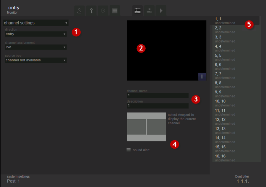
This tab is used for connection of video sources and display options. The exterior view of the tab is shown in fig. Channel settings. “Settings” tab.
The tab consists of 5 parts:
- type of configuration ( Channel settings or Image Parameters) and its parameters;
- viewport - to display video from the selected source;
- fields for editing the name and description of the selected channel;
- position to determine the viewport for displaying the selected channel in monitoring mode;
- channel list.
Channel settings
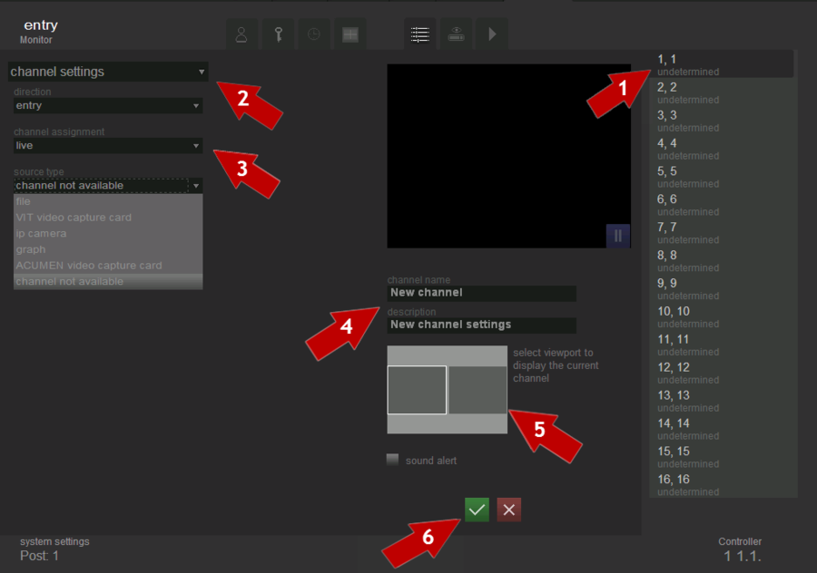
To configure the channel it is needed to do the following actions in order to configure the channel (see fig. Channel settings.Settings sequence):
- select a channel from the channel list, that you want to configure;
- select the type of configuration- “channel settings”;
- set channel parameters;
- set its name and description(if necessary);
- select the viewport in which the video of the current channel will be displayed on the “Live” tab;
- click the “Save”
 button.
Channels list
List of channels, their names, designation and description - clicking on an entry in this list determines which channel is configured at the moment. Settings for each channel are unique and do not depend on the configuration of other channels, except for resolution settings and color space for video capture card, which must be the same for each channel on a particular processor board.
Channel parameters settings
While configuring channels parameters it’s necessary to indicate the motion direction, the channel purpose and the type of source for receiving the data.
Motion direction
Direction – is a setting used to define vehicles motion directions.
If motion direction is marked as “entry”, then all the vehicles having plate numbers, recognized on this channel, are considered as entering to the parking lot. Then, operator can allow vehicle to enter to the parking lot. Thereafter, time of parking starts to count down for the vehicle.
If motion direction is marked as “exit”, then all the vehicles having plate numbers, recognized on this channel, are considered as leaving the parking lot. Then, operator can allow vehicle to leave the parking. In this case system withdraws money from owner’s balance in accordance to parking time and rate.
If motion direction is marked as “undefined”, then operator can manually set motion direction of vehicle with recognized plate number.
Thus, if there are different cameras for object entry and exit, and video flow from these cameras is displayd on different channels, then each channel should have settings “entry” or “exit” appropriatly. Otherwise, when for entry and exit there is only one camera, the direction setting should have “undefined” value.
Attention!
Wrong values for this setting may lead to uncorrect system work. For example, if motion direction of channel is set as “entry”, and really this channel is on exit, then after number plate recognition system will display red alert, which means some type of error. Detailed description of system messages for entries and exits read in “Events” tab manual.
Channel purpose
Channel purpose – is a setting which is needed to determine the operation mode of the channel.
- live - the mode in which the recognition of number plates is not made;
- parking - the mode in which the recognition of number plate is made, although, an operator should manually allow entries and exits for the vehicles.
Attention!
As there is no number plates recognition in “live” mode, so there is no time and parking cost evaluating.
Source type
Source type - is a setting which determines how the video flow and the parameters of its transmission are transferred to the system.
File
This source type is used when it is necessary to recognize license plates from existing on the computer video files (such as recorded video archive).
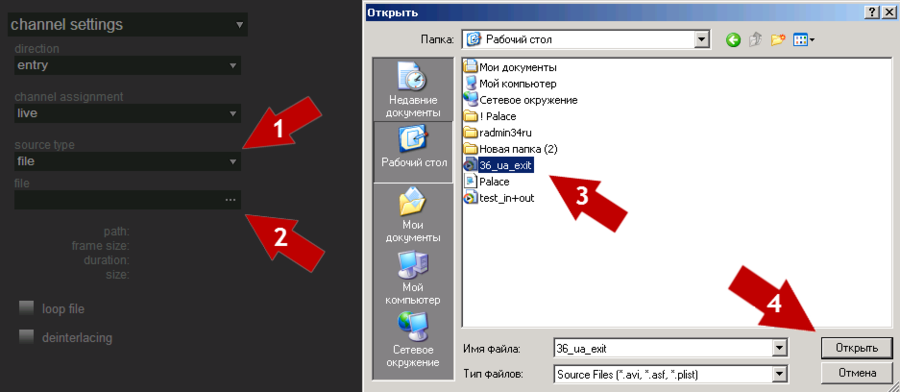
In order to select and configure the file as a data source it is necessary to perform the following steps consistently (see fig. Channel settings. Selecting video file):
- select source type – file;
- click the
 button “file” in the filed file;
 - select the file that must be opened;
- click the button “Open”;
- configure the video flow transmission parameters.
It is possible to play not only single files, but play-lists. To set play-list as a video source after click on a button ![]() «File» it is nesessary to choose not single file, but play-list, that was cheated before.
«File» it is nesessary to choose not single file, but play-list, that was cheated before.
When the file or play list is selected, it is possible to specify looping and de-interlacing options.
The selection of the option “loop file” leads to the fact that after the end of the selected file it starts to play again. If this option is not selected, then after the end of the file it stops to play. In order to loop the file, it is necessary to put the flag next to the option “loop file”.
The selection of the option "deinterlace" applies the filter required to eliminate the effect of interlacing to the selected video. In the case of interlacing, which arises when combining the previous half-frame with the current one (e.g. the even lines- from the current half-frame and odd- from the previous one) in the video of interlaced format, the edges of lenses have the form of comb (see fig. Frame with interlacing) which significantly affects the recognition quality.
To get rid of this unpleasant effect and to improve the recognition quality one must select the option “deinterlacing”.
Video capture board
This type of data source is used when you want to receive the video flow from analog cameras.
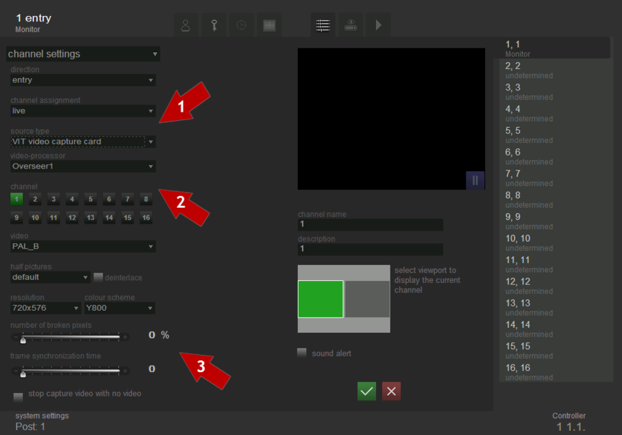
In order to select and configure the video capture card as a data source it is necessary to perform the following steps consistently (see fig. Channel settings. Capture board adjustment):
- select source type - video capture card;
- select a video flow processor and a channel;
- configure the video flow transmission parameters.
When the video capture card is selected as a video source, video transmission parameters can be set for it.
Capture card – allows to select a video flow processor (Overseer1, Overseer2, Overseer3, Overseer4). Each of these processors handles up to 50 half-frames (board handles up to 200 half-frames). In case when the system processes from 2 to 4 recognition channels, if it is possible, channels are distributed by one for each processor.
Attention!
If one processor is required to recognize numbers of vehicles from more than one camera, the characteristics of the input video flow (resolution, color) should be identical.
Channel. Every Overseer card has 16 channels for connecting cameras. Channel corresponds to a number on the connector of the camera adapter (DB25-16BNC), to which the camera is connected.
Video. Overseer supports two video flow transmission standards: PAL_B and NTSC_M. Video format and resolution settings should be adjusted according to the video source and required image in the channel.
Half-frames. Default settings for half-frames are recommended; change it, only if the image "tears" by 1-2 pixels.
The selection of the option "deinterlace" applies the filter required to eliminate the effect of interlacing to the selected video. . In the case of interlacing, which arises when combining the previous half-frame with the current one (eg the even lines- from the current half-frame and odd- from the previous one) in the video of interlaced format, the edges of lenses have the form of comb (see fig. Channel settings. Frame with interlacing) which significantly affects the recognition quality.
Resolution. This field is for choosing necessary resolution. Raising resolution in direct ratio affects quality of recognition and inversely affects the velocity of the data transmission.
Color space. For black and white images it is recommended to use a color space Y800; for color images — UYUY.
The number of broken pixels, % - defines % of broken pixels, and the increase of which brings to the discard frame. “Broken" are pixels ("pixels" - it is the code name in this case, in fact it is the bytes), which were transferred at a time when the internal buffer was full. In the picture at this time, there is the string that contains the image of the previous frame. For each GPU has a counter of "broken" bytes. After the successful capturing, the counter value is read, and if the settings are discarded, depending on the value of the counter, half-frame can be discarded. With regular overflows it can improve the image quality due to the number of frames per second.
The time of the frame synchronization – when multiplexing of different camcorders, video processor has no time to reinitialize, then occurs the vertical synchronization and the capture begins with any half-frame row. To avoid this situation, one can set the number of rows to skip before the image capture, then one or more half-frames are being skipped and the video processor has time to synchronize with the image.
Stop capture video without video signal - when placing this flag the video capture without video signal is stopped. This reduces the load on the system and multiplexing can increase the number of frames per second in the other filters, in which video source is present.
IP camera Axis
This type of cameras is used in case the video flow should be taken from Axis IP-cameras.
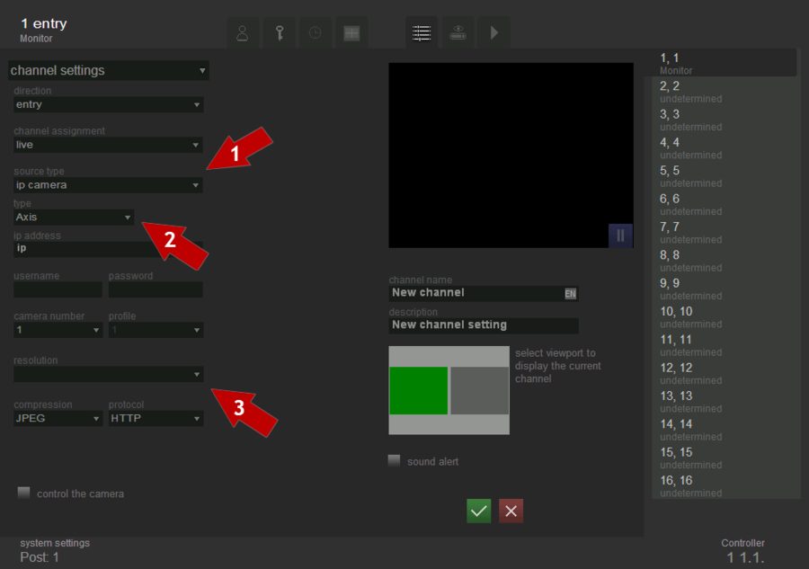
To select and configure Axis IP-camera as the data source, one must perform consistently the following steps (see figure Channel settings. Selection and configuration of Axis IP-camera as the video source):
- select source type - IP-camera;
- select type of the camera - Axis;
- configure the video flow transmission parameters.
When Axis IP-camera is selected as the video source, the video stream transmission parameters can be set for it.
IP address. Enter the IP-address of the camera into this field in format ххх.ххх.ххх.ххх:хххх. Enter the IP-address of the camera before “:” and after this symbol enter the number of the port. Also, entering for this type of camera is possible in format www.xxxxx.xхx:xxxx, where before “:” state URL of the camera, and after “:” enter the number of port.
Login and password. In these fields login and password should be entered for access to the IP-camera. They may be required both for observation and camera management.
Camera’s number. If IP-coder with one or more connected cameras is used, then state in this field number of the camera, video flow from which should be processed.
Profile and Resolution fields do not have to be filled. Camera settings are being used for this type of cameras.
Compression. In this field state required compression. M-JPEG, MPEG-4 and Н.264 formats are being supported for Axis IP-cameras.
Protocol. This field is for choosing the data transfer protocol. HTTP, MCUST, HTTPS, RTSP protocols are supported for Axis IP-cameras.
Camera control. This setting turns on management of the IP-camera.
IP camera Bosh
This type of cameras is used in case the video flow should be taken from Bosh IP-cameras.
This type of data source is used when the video flow must be received from Bosh IP-camera.
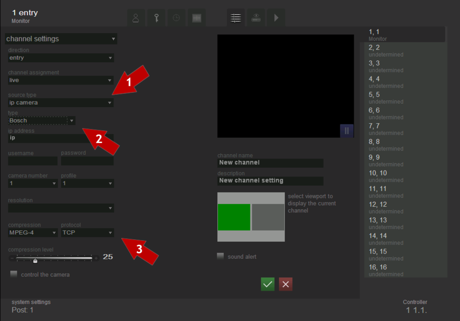
To select and configure Bosh IP-camera as the data source, one must perform consistently the following steps (see figure Channel settings. Selection and configuration of Bosh IP-camera as the video source):
- select source type- IP-camera;
- select type of the camera- Bosh;
- configure the video flow transmission parameters.
When Bosh IP -camera is selected as the video source, the video stream transmission parameters can be set for it.
IP address. Enter the IP-address of the camera into this field in format ххх.ххх.ххх.ххх:хххх. Enter the IP-address of the camera before “:” and after this symbol enter the number of the port. Also, entering for this type of camera is possible in format www.xxxxx.xхx:xxxx, where before “:” state URL of the camera, and after “:” enter the number of port.
Login and password. In these fields login and password should be entered for access to the IP-camera. They may be required both for observation and camera management.
Camera’s number. If IP-coder with one or more connected cameras is used, then state in this field number of the camera, video flow from which should be processed.
Profile. If device renders video signal in number of flows, then state in this field number of the flow, signal from which should be processed.
Resolution field does not have to be filled. Camera settings are being used for this type of cameras.
Compression. This field allows to select encoding and decoding options for video transmission - to view, the formats JPEG, MPEG-4 и Н.264 are supported for Bosh IP-camera.
Protocol. This field is for choosing the data transfer protocol. TCP, UDP, Multicast protocols are supported for Bosch IP-cameras.
Compression level. This field is for choosing necessary compression level. Raising compression level inversely affects quality of recognition and in direct ratio affects the velocity of the data transmission. Permissible value range is from 1 to 100.
IP camera Arecont Vision
This type of cameras is used in case the video flow should be taken from Arecont Vision IP-cameras.
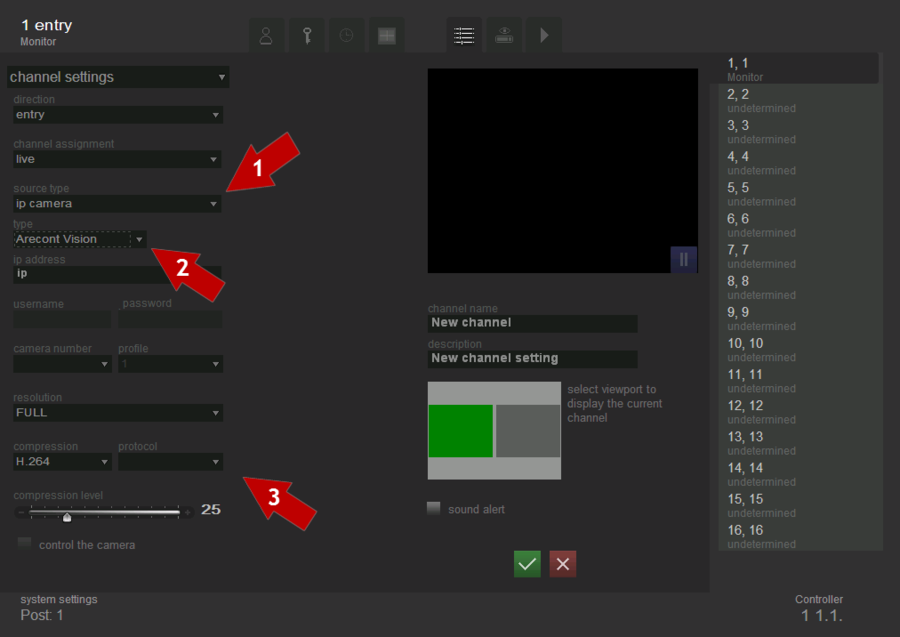
To select and configure the Arecont Vision IP-camera as the data source, one must perform consistently the following steps (see figure Channel settings. Selection and configuration of Arecont Vision ip-camera as the video source):
- select source type- IP-camera;
- select type of the camera- Arecont Vision;
- configure the video flow transmission parameters.
IP address. Enter the IP-address of the camera into this field in format ххх.ххх.ххх.ххх:хххх. Enter the IP-address of the camera before “:” and after this symbol enter the number of the port.
Fields Login, Password, Camera’s number, Profile and Protocol do not have to be filled for this type of cameras. Also, option Camera control is not available for these cameras.
Resolution. This field is for choosing necessary resolution. Raising resolution in direct ratio affects quality of recognition and inversely affects the velocity of the data transmission. FULL and HALF types of resolution are available for Arecont Vision IP-cameras.
Compression. In this field state required compression. M-JPEG and Н.264 formats are being supported for Arecont Vision IP-cameras.
Compression level. This field is for choosing necessary compression level. Raising compression level inversely affects quality of recognition and in direct ratio affects the velocity of the data transmission. Permissible value range is from 1 to 100.
IP camera Mobotix
This type of cameras is used in case the video flow should be taken from Mobotix IP-cameras.
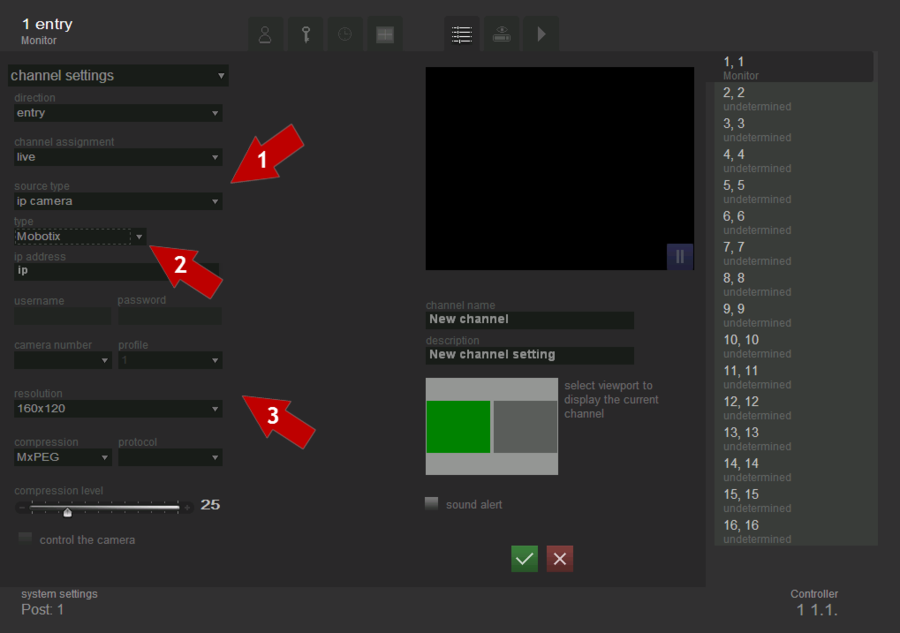
To select and configure Mobotix IP-cameras as the data source, one must perform consistently the following steps (see figure Channel settings. Selection and configuration of Mobotix IP-camera as the video source):
- select source type-IP-camera;
- select type of the camera- Mobotix;
- configure the video flow transmission parameters.
IP address - in this field you must enter the IP-address of the camera, in the format xxx.xxx.xxx.xxx:xxxx, where up to ':' - it's just IP-address of the camera, and after - the port number.
Fields Login, Password, Camera Number, Profile and Protocol shall not be filled for this type of cameras. This type of cameras does not have the option to control the camera.
Resolution. This field is to select the necessary resolution. Raising the resolution in direct ratio affects the quality of recognition, and inversely affects the velocity of data transmission For Mobotix Ip-cameras the following types of resolutions are available: 160 * 120 320 * 240 640 * 480, 1280x960, 2048 * 1536.
Compression. This field specifies the necessary compression, JPEG and MhPEG formats are being supported for Mobotix Ip-cameras.
Compression level. This filed allows you to select the necessary compression level. Raising compression level inversely affects quality of recognition and in direct ratio affects the velocity of the data transmission. Valid values are: from 1 to 100.
IP camera Panasonic
This type of cameras is used in case the video flow should be taken from Arecont Vision IP-cameras.
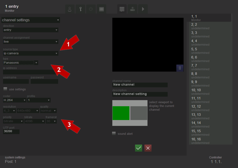
To select and configure Panasonic IP-camera as the data source, one must perform consistently the following steps (see fig. Channel settings. Selection and configuration of Panasonic IP-camera as the video source):
- select source type - IP-camera;
- select type of the camera-Panasonic;
- configure the video flow transmission parameters.
IP address. Enter the IP-address of the camera into this field in format ххх.ххх.ххх.ххх:хххх. Enter the IP-address of the camera before “:” and after this symbol enter the number of the port.
Login and password. In these fields login and password should be entered for access to the IP-camera.
Turning on option Use settings enables user’s settings of resolution, quality and priority of video processing. If this option is turned off, camera settings are being used. You should be careful with manual settings, because in most cases camera settings can be fixed more precisely for a specific task.
Compression. In this field state required compression. JPEG and Н.264 formats are being supported for Panasonic IP-cameras.
Profile. If device renders video signal in number of flows, then state in this field number of the flow, signal from which should be processed.
Resolution. This field is for choosing necessary resolution. Raising resolution in direct ratio affects quality of recognition and inversely affects the velocity of the data transmission. 16_9 (320*180, 640*360, 1280x720, 1920*1080) and 4_3 (320*240, 640*480, 960*720, 1280x960, 2048*1536) types of resolution are available for Panasonic IP-cameras.
Quality. This field is for choosing necessary quality of video that is being processed. Low, Normal and Fine types of resolution are available for Panasonic IP-cameras.
Priority. Priority of data transfer parameter is stated in this field. Bitrate or framerate priority is available for Panasonic IP-cameras.
Bitrate. Defines the maximum number of bites that can be transferred per one unit of time.
Framerate. Defines the number of frames that are transferred per one second.
UTP-port. Port that receives data flow should be set in this field. Is being used only for MPEG-4 and h.264. Port for each channel should be unique within one computer.
IP camera ACTi
This type of cameras is used in case the video flow should be taken from ACTi IP-cameras.
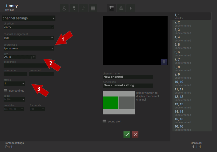
To select and configure ACTi ip-camera as the data source, one must perform consistently the following steps (see fig. Channel settings. Selection and configuration of ACTi ip-camera as the video source):
- select source type- IP-camera;
- select type of the camera- ACTi;
- configure the video flow transmission parameters.
IP address - in this field you must enter the Ip-address of the camera, in the format xxx.xxx.xxx.xxx:xxxx, where up to ':' - it's just IP-address of the camera, and after - the port number.
Login and password. In this fields you should enter the login and password for access to the IP-camera.
Profile. If the device gives the video a few streams, then the flow number indicates in this field, from which must to be handled the signal.
Turning the option Use settings enables user’s settings of resolution, quality and priority of video processing. If this option is turned off, camera settings are being used. One should be careful with manual settings, because in most cases camera settings can be fixed more precisely for a specific task.
The encoder (compression). This field specifies the necessary compression, Н.264, MJPEG и MPEG4 formats are being supported for ACTi IP-cameras.
Resolution. This field is to select the necessary resolution. Increasing the resolution effects directly proportional on the quality of recognition, and is inversely proportional to the speed of data transmission. The following types of resolutions are available for ACTi IP-cameras: 160*112, 320*240, 640*480, 1280x720, and 1280x960.
Framerate. Defines the number of frames that are transferred per one second. In the ACTi IP –camera 1, 2, 5, 10, 15 и 30 frames per second can be transferred.
IP camera Basler
This type of cameras is used in case the video flow should be taken from Basler IP-cameras.
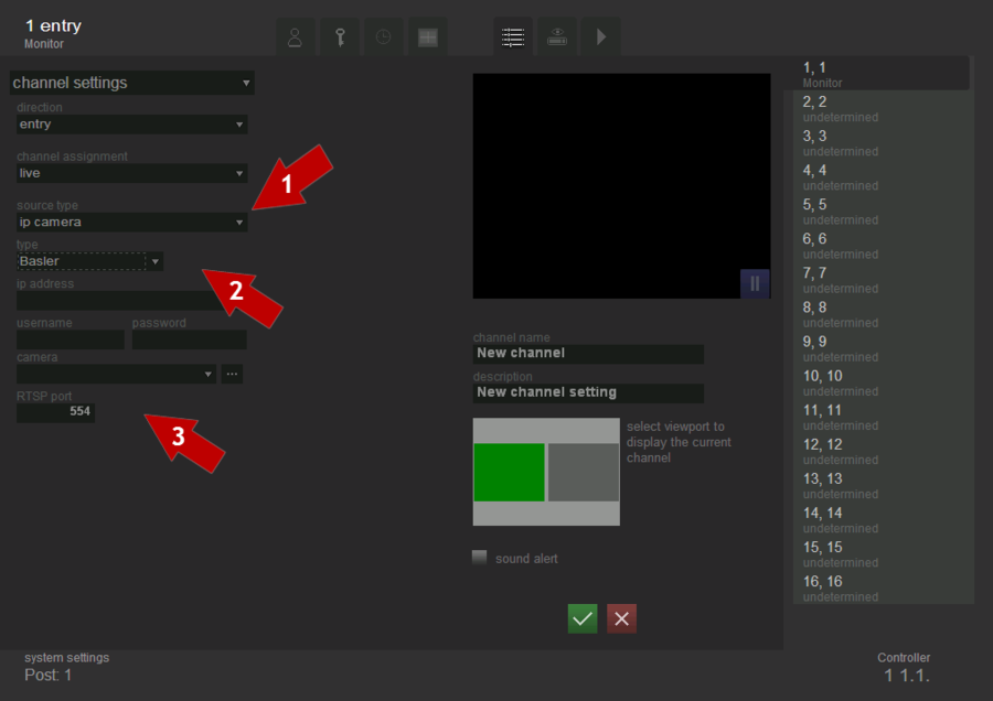
To select and configure the Basler IP-camera as the data source, one must perform consistently the following steps (see fig. Channel settings. Selection and configuration of Basler IP-camera as the video source):
- select source type-IP-camera;
- select type of the camera- Basler;
- configure the video flow transmission parameters.
IP address - in this field you must enter the IP-address of the camera, in the format xxx.xxx.xxx.xxx:xxxx, where up to ':' - it's just IP-address of the camera, and after - the port number.
Login and password. In this field you should enter the login and password for access to the IP-camera.
Camera. This field is used to select a particular camera, video of which will be displayed in the viewport.
The Button ![]() is used to create the list of available cameras. When clicking, a list of available cameras appears in the drop-down box “Camera”.
is used to create the list of available cameras. When clicking, a list of available cameras appears in the drop-down box “Camera”.
RTSP-port. This field specifies the port that receives data flow. Port for each channel must be unique within one computer.
IP camera Overseer Video
This video source type should be applied in case you need get a video flow from another Overseer Traffic installed in other computer. The description on how to configure Overseer Traffic, which is the video source, is represented in the “Managing users and access setting” guide, section “Remote Access”.
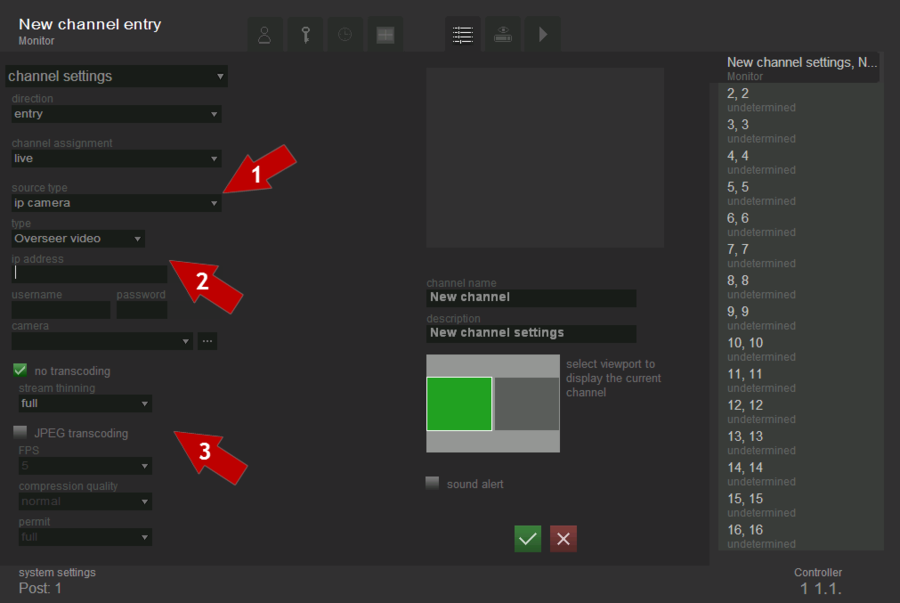
To select and configure the Overseer Video IP-camera as the data source, one must perform consistently the following steps (see fig. Channel settings. Selection and configuration of the Overseer Video IP-camera as the video source):
- select source type - IP-camera;
- select type of the camera-Overseer Video;
- configure the video flow transmission parameters.
IP address - in this field you must enter the IP-address of the camera, in the format xxx.xxx.xxx.xxx:xxxx, where up to ':' - it's just IP-address of the camera, and after - the port number.
Login and password. In this field you should enter the login and password for access to the Overseer Video IP-camera.
Camera. This field is used to select a particular camera, the video of which will be displayed in the viewport.
The Button ![]() is used to create the list of available cameras. When clicking, a list of available cameras appears in the drop-down box ”Camera”.
is used to create the list of available cameras. When clicking, a list of available cameras appears in the drop-down box ”Camera”.
Without decoding - it is a flag, indicating the absence of the need to convert the received data. If this flag is put, then it is possible to set parameters of thinning flow - full, only key, only 2-d key, only 3-d key, only 4-d key, only 5-d key, only 10-d key, only 25 -d key.
JPEG decoding - it is a flag indicating the need to convert data into jpeg. If the flag is put, then it is possible to set FBS, compression quality and resolution.
FPS. Specifies the number of frames transmitted per second. The following FPS parameters are supported for the Overseer Video IP-cameras: 0.2, 0.5, 1, 2, 5, 10, 15, 25, 30.
Compression quality. This field is used to select the necessary quality of the processing video. The following types are supported for the Overseer Video IP-camera: draft, low, normal, high и best.
Resolution. This field is to select the necessary resolution. Raising the resolution in direct ratio affects the quality of recognition, and inversely affects the velocity of data transmission. Three types of resolution are available for Overseer Video IP-camera: FULL 1/4 и 1/6.
IP camera Generic
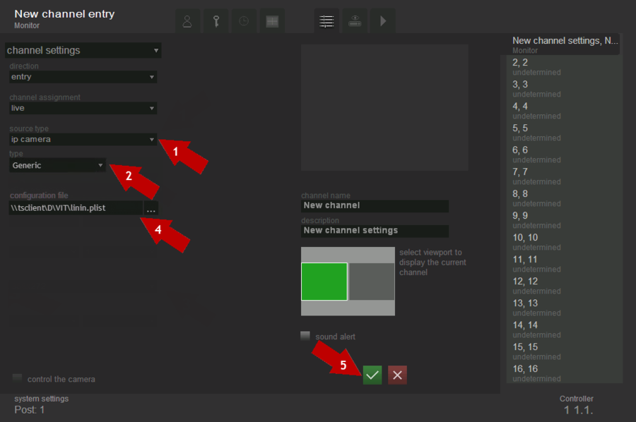
It is availiable to view Generic video stream in RTSP format using Generic Camera type. Work mode of generic camera type depends on the type of videostream which can be transmitted by RTSP, for example: MJPEG, H264.
To select and configure the Generic as the data source, one must perform consistently the following steps (see fig. Channel settings. Selection and configuration of Generic type of IP-camera as the video source):
- select source type- ip-camera;
- select type of the camera-Generic;
- create configuration file which defines connection settings to the Generic RTSP video stream. This file should contain values of access variables:
- deviceID. This field should have physical number of camera device.
- async . It is recommended to put "TRUE" as the value of this field.
- full_url. This field should contain an actual url-address of connection to the videostream.
- force_tcp. It is recommended to put "TRUE" as the value of this field.
Example
This example shows content of the configuration file "settings.plist " for connection to the video stream (the other file name is also possible):
- deviceID = "{B95054AC-672D-4A03-A75E-9DAAB34BDCA2}";
- async = "TRUE";
- full_url = "rtsp://admin:pass@192.168.100.26/rtsph2641080p";
- force_tcp = "TRUE";
- select the file created in the 3rd paragraph as the configuration file;
- save changes in settings.
How to control IP-camera
To control IP-camera point "control the camera" in the settings should be checked. To prevent accidental miscontrol, all management should be performed with the “Shift” key pressed.
- "shift+click" on any place of the viewport focuses the camera on this point. Rotation of mouse wheel zooms image in/out.
Steps described above set the camera to so-called "default" position (as it was adjusted in settings).
In the “Live” mode it is also acceptable to control the camera while the "Shift" key is pressed. When the "Shift" key is pressed, all alerts, channels names and all other control buttons of the viewport are hidden (to let the operator see, what is "behind the alert").
"Shift+Space" or clicking on the special icon next to the channel name, returns camera settings to the default state.
DevLine board
This type of cameras is used in case the video flow should be taken from DevLine boards.
Preliminary for the board’s correct setting it is necessary to go to the Start-All Programs- Line- Observation post- call the item “Administration” in menu and select any camera. In the general settings tab, change the parameter speed (fps) from 8 to 12. Press the button "Apply to all" and then “Save and exit". Close the “Observation post”.
To select and configure video flow from DevLine board as the data source, it’s necessary to perform consistently the following steps (see fig. Channel settings. Selection and configuration of the DevLine board as the video source):
- select source type- IP-camera;
- select type of the camera – DevLine;
- configure the video flow transmission parameters.
IP address - in this field you must enter the Ip-address of the camera, in the format xxx.xxx.xxx.xxx:xxxx, where up to ':' - it's just IP-address of the camera, and after - the port number. If the Video board is installed on the local computer then the address bar will be 127.0.0.1. If the board is located on a remote computer, to access it you must enter the IP address of the computer on which this board is installed (for ex. 195.168.100.1).
Login and password. In this field you should enter the login and password for access to the IP-camera. Login “admin” and the blank password are set for the board DevLine.
Camera. This field is used to select a particular camera, the video of which will be displayed in the viewport.
The Button ![]() is used to create the list of available cameras. When clicking, a list of available cameras appears in the drop-down box “Camera”.
is used to create the list of available cameras. When clicking, a list of available cameras appears in the drop-down box “Camera”.
Resolution. This field is to select the necessary resolution. Raising the resolution in direct ratio affects the quality of recognition, and inversely affects the velocity of data transmission. The following types of resolution are available for the board DevLine: 360*288, 720*288, 720*576.
Framerate. Defines the number of frames that are transferred per one second. Valid values are 15, 20, 25.
Quality. This field enables to select the required quality of the processed video.
Attention!
If after you changed some channel settings such as resolution, quality and framerate you have got an "ERROR" notification in the preview window , there is a need to go to Services (Start - Control Panel - Administrative Tools - Services), and restart the services "DevLine kernel service" and "DevLine oopnet” service.
Optimal configurations. Resolution settings 720 * 576 is not recommended for use. Optimum settings for resolution - 720* 288, for the quality - 70 or 80, framerate should be 20 - 25.
Graph
This type of data source is used if it is necessary to recognize car number plates from the devices, settings of which are not handed to the interface, but which works with DirectShow filters.
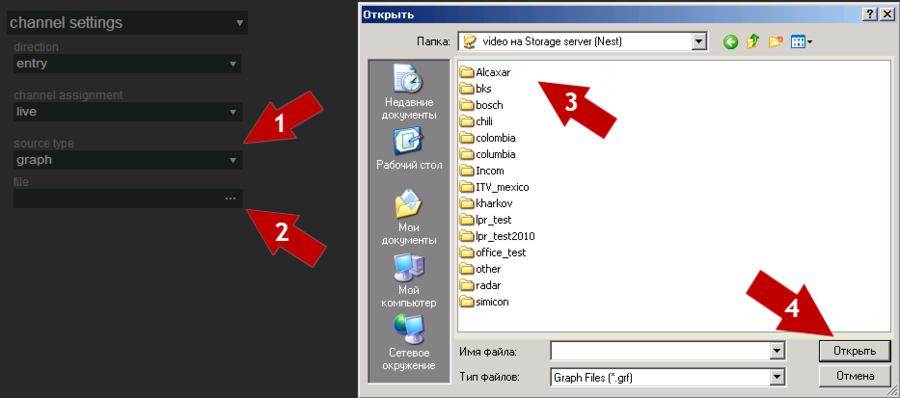
To select and configure the count as the data source, you should perform consistently the following steps (see fig. Channel settings. Selection of graph as the type of video source):
- select source type - graph;
- click the button
 “File” in the file field;
 - select the required graph to be used;
- click the button ”Open”.
ACUMEN board
This type of cameras is used in case the video flow should be taken from Acumen boards.
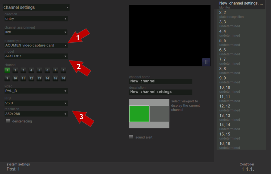
In order to select and configure the video capture board Acumen as the data source, you should perform consistently the following steps (see fig. Channel settings. Selection of video capture board Acumen as the source of video):
- select source type - board Acumen;
- select the board type;
- select the channel;
- configure the video flow transmission parameters.
When Acumen board is selected as the source of video, video flow transmission parameters can be set for it.
Board model - this option allows you to specify the model used by the board. For today, Overseer Traffic supports the following types of boards Acumen: Ai-SC367, Ai-SC387, Ai-SC347, Ai-SC165, Ai-SC185, Ai-SC145, Ai-SC333, Ai-BOX, Ai-SC310.
Channel - each board Acumen has from 4 to 16 channels for connecting video cameras (the number of channels depends on the model Acumen). It complies with the number of connectors on the adapter to connect the cameras (DB25-16BNC), to which the given camera is connected.
Video Standard. Overseer supports two standards of video flow transmission PAL_B and NTSC_M. Settings of the video format and resolution should be set according to the used video source and the required image in the channel.
FPS. Determines the number of frames transmitted per second. The valid values are 25,12.5, 6.25, 3.125
Resolution. This field is to select the necessary resolution .Raising the resolution in direct ratio affects the quality of recognition, and inversely affects the velocity of data transmission. The valid resolutions depend on the type of Acumen board’s model.
The selection of the option "deinterlace" applies the filter required to eliminate the effect of interlacing to the selected video. In case of interlacing, which arises when combining the previous half-frame with the current one (eg. the even lines - from the current half-frame and odd - from the previous one) in the video of interlaced format, the edges of lenses have the form of comb (see fig. Channel settings. Frame with interlacing'Italic text) which significantly affects the recognition quality.
Channel name and description
The channel name and its description are intended to facilitate the work of operators. For example, specifying the location of the camera in future could greatly accelerate processing of information by the operator; since he will not have to guess from which camera the image was received.
Viewport’s selection
When choosing the viewport for display on the "Live" tab one should pay attention to the following notation:
- gray viewport - free, can be selected to display the video flow;
- green viewport - selected at the moment to display the video flow;
- red viewport - is in use by another channel, can not be selected to display the video flow.
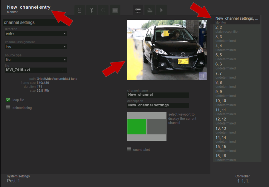
If the setting is done correctly, then the following changes will occur on the tab “Channel Settings” (fig. Channel settings. Configured channel):
- the name of the channel, the motion direction and its purpose (in case it is specified) will appear in the upper right corner;
- video flow from selected source will appear in viewport for displaying video;
- channel description and its assignment will appear in the channel list.
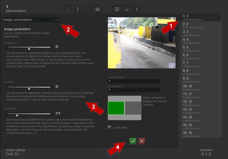
Image parameters settings
A description of the channel and its purpose will appear in the channel list. In order to configure the image, one must perform the following steps (see fig. Channel settings. Setting image parameters):
- select a channel form the channel list, which you want to configure;
- select the type of setting- “ Image Settings”;
- set image settings;
- click the button
 “ Save”.
Brightness
This setting provides software brightness control of the frame that is being recognized. It is recommended to adjust this setting if you know that the object of observation will have a non-standard lighting (shaded or highlighted).
Attention!
Changes of this setting are not visible for an operator; they can be tracked back by frames in the "Events" tab.
Contrast
This setting provides software contrast control of the frame that is being recognized.
Attention!
Changes of this setting are not visible for an operator; they can be tracked back by frames in the "Events" tab
Threshold
This setting determines capturing sensitivity. Contrast between the color of alphanumeric signs and license plates depends on the brightness and contrast of the incoming frame. Reducing this setting enables better recognition of dirty plates; increasing this setting allows recognition of clean plates only. Recommended value — 21.
Channel configuration in Overseer Parking Настройка канала в системе Overseer Parking Configuración de canal en Overseer Parking
