Channel configuration in AutoCode for VMS Parking
Connection of video sources
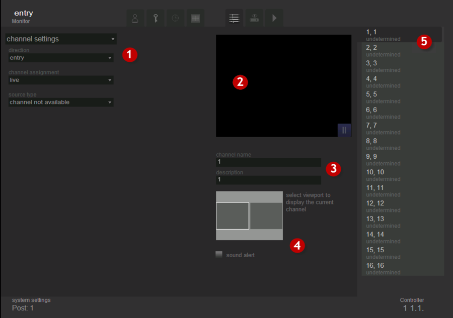
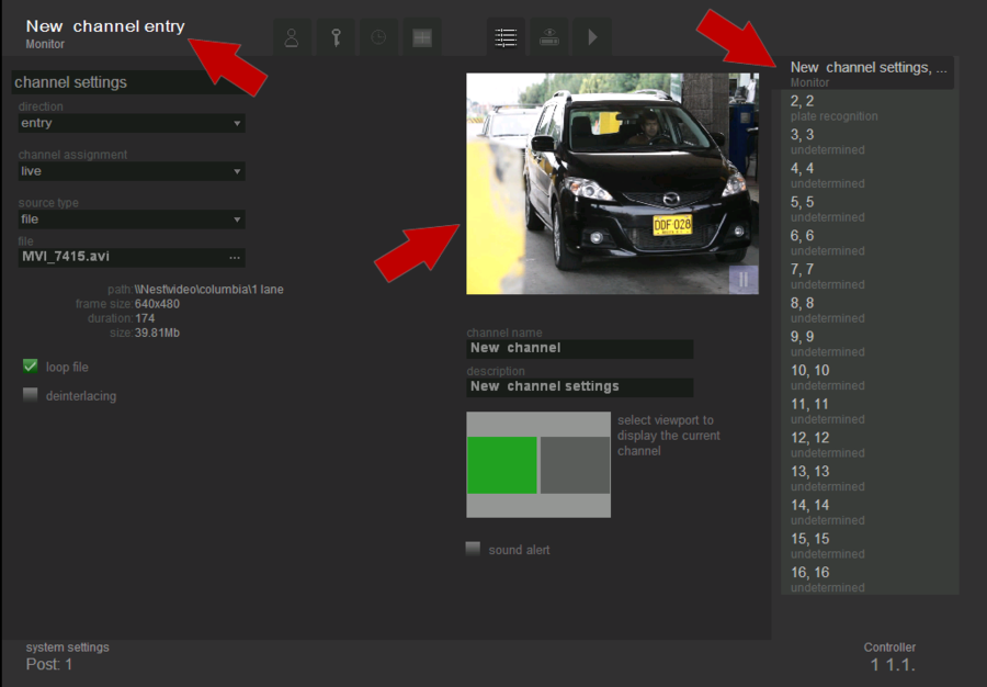
This tab is used for connection of video sources and display options. The exterior view of the tab is shown in fig. Channel settings. “Settings” tab.
The tab consists of 5 parts:
- type of configuration ( Channel settings or Image Parameters) and its parameters;
- viewport - to display video from the selected source;
- fields for editing the name and description of the selected channel;
- position to determine the viewport for displaying the selected channel in monitoring mode;
- channel list.
Channel settings
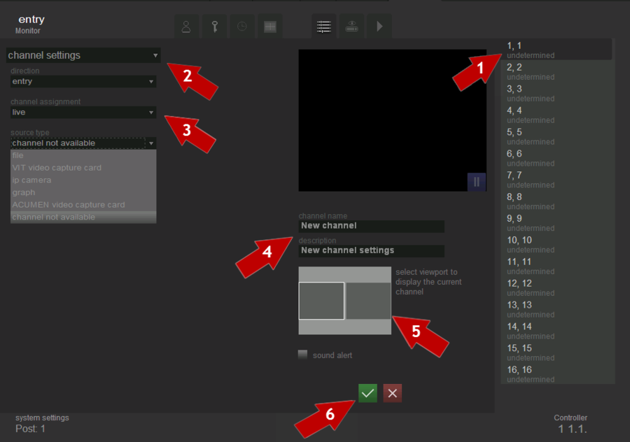
To configure the channel it is needed to do the following actions in order to configure the channel (see fig. Channel settings.Settings sequence):
- select a channel from the channel list, that you want to configure;
- select the type of configuration- “channel settings”;
- set channel parameters;
- set its name and description(if necessary);
- select the viewport in which the video of the current channel will be displayed on the “Live” tab;
- click the “Save”
 button.
Channels list
List of channels, their names, designation and description - clicking on an entry in this list determines which channel is configured at the moment. Settings for each channel are unique and do not depend on the configuration of other channels, except for resolution settings and color space for video capture card, which must be the same for each channel on a particular processor board.
Channel parameters settings
While configuring channels parameters it’s necessary to indicate the motion direction, the channel purpose and the type of source for receiving the data.
Motion direction
Direction – is a setting used to define vehicles motion directions.
If motion direction is marked as “entry”, then all the vehicles having plate numbers, recognized on this channel, are considered as entering to the parking lot. Then, operator can allow vehicle to enter to the parking lot. Thereafter, time of parking starts to count down for the vehicle.
If motion direction is marked as “exit”, then all the vehicles having plate numbers, recognized on this channel, are considered as leaving the parking lot. Then, operator can allow vehicle to leave the parking. In this case system withdraws money from owner’s balance in accordance to parking time and rate.
If motion direction is marked as “undefined”, then operator can manually set motion direction of vehicle with recognized plate number.
Thus, if there are different cameras for object entry and exit, and video flow from these cameras is displayd on different channels, then each channel should have settings “entry” or “exit” appropriatly. Otherwise, when for entry and exit there is only one camera, the direction setting should have “undefined” value.
Attention!
Wrong values for this setting may lead to uncorrect system work. For example, if motion direction of channel is set as “entry”, and really this channel is on exit, then after number plate recognition system will display red alert, which means some type of error. Detailed description of system messages for entries and exits read in “Events” tab manual.
Channel purpose
Channel purpose – is a setting which is needed to determine the operation mode of the channel.
- live - the mode in which the recognition of number plates is not made;
- parking - the mode in which the recognition of number plate is made, although, an operator should manually allow entries and exits for the vehicles.
Attention!
As there is no number plates recognition in “live” mode, so there is no time and parking cost evaluating.
Source type
Source type - is a setting which determines how the video flow and the parameters of its transmission are transferred to the system.
File
This source type is used when it is necessary to recognize license plates from existing on the computer video files (such as recorded video archive).
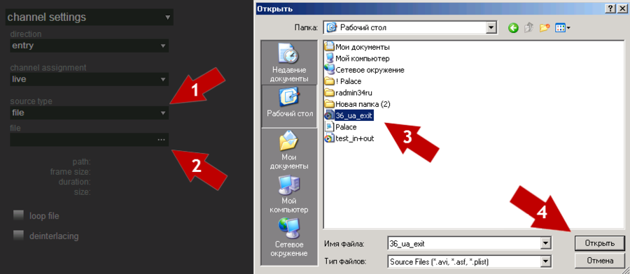
In order to select and configure the file as a data source it is necessary to perform the following steps consistently (see fig. Channel settings. Selecting video file):
- select source type – file;
- click the
 button “file” in the filed file;
 - select the file that must be opened;
- click the button “Open”;
- configure the video flow transmission parameters.
It is possible to play not only single files, but play-lists. To set play-list as a video source after click on a button ![]() «File» it is nesessary to choose not single file, but play-list, that was cheated before.
«File» it is nesessary to choose not single file, but play-list, that was cheated before.
When the file or play list is selected, it is possible to specify looping and de-interlacing options.
The selection of the option “loop file” leads to the fact that after the end of the selected file it starts to play again. If this option is not selected, then after the end of the file it stops to play. In order to loop the file, it is necessary to put the flag next to the option “loop file”.
The selection of the option "deinterlace" applies the filter required to eliminate the effect of interlacing to the selected video. In the case of interlacing, which arises when combining the previous half-frame with the current one (e.g. the even lines- from the current half-frame and odd- from the previous one) in the video of interlaced format, the edges of lenses have the form of comb (see fig. Frame with interlacing) which significantly affects the recognition quality.
To get rid of this unpleasant effect and to improve the recognition quality one must select the option “deinterlacing”.
IP camera “VMS”
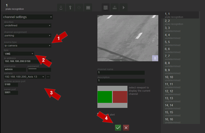
To select and configure video from VMS (Video Management System) MainConsole application as the data source, it’s necessary to perform consistently the following steps (see figure Channel settings. Selection and configuration of the VMS MainConsole application as the video source):
- select source type – IP-camera ;
- select type of the camera - VMS;
- configure the video flow transmission parameters.
IP address. In this field it is necessary to enter the ip-address of MainConsole application server, in the format xxx.xxx.xxx.xxx:xxxx, where up to ':' - it's ip-address of the camera, and after - the port number. If the MainConsole application is installed on the local computer then the address bar will be 127.0.0.1.
Login and password. In this field it is necessary to enter the login and password for access to the MainConsole application. Configure MainConsole application to define users’ accounts and settings.
Camera. This field is used for selection of an ip-camera, which video will be displayed in the viewport.
The Button ![]() is used to create the list of available cameras. When clicking, a list of available cameras appears in the drop-down box ”Camera”.
is used to create the list of available cameras. When clicking, a list of available cameras appears in the drop-down box ”Camera”.
Archive access port. In this field it is necessary to enter port’s number for archive data getting. Number, which must be set in this field, also located at MainConsole application -> General setting -> Network services -> Remote play back.
Server port. In this field it is necessary to enter port’s number for sending data from AutoCode to VMS. Number, which must be set in this field, also located at MainConsole application -> General setting -> Metadata Application -> Metadata Source setting -> Port.
Channel name and description
The channel name and its description are intended to facilitate the work of operators. For example, specifying the location of the camera in future could greatly accelerate processing of information by the operator; since he will not have to guess from which camera the image was received.
Viewport’s selection
When choosing the viewport for display on the "Live" tab one should pay attention to the following notation:
- gray viewport - free, can be selected to display the video flow;
- green viewport - selected at the moment to display the video flow;
- red viewport - is in use by another channel, can not be selected to display the video flow.
If the setting is done correctly, then the following changes will occur on the tab “Channel Settings” (fig. Channel settings. Configured channel):
- the name of the channel, the motion direction and its purpose (in case it is specified) will appear in the upper right corner;
- video flow from selected source will appear in viewport for displaying video;
- channel description and its assignment will appear in the channel list.
Image parameters settings
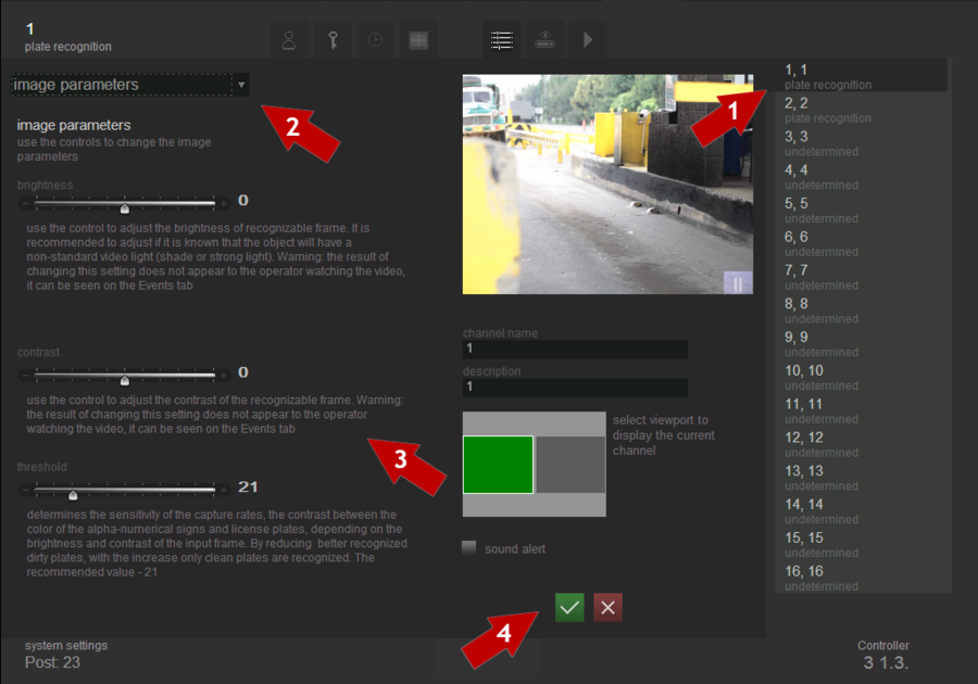
A description of the channel and its purpose will appear in the channel list. In order to configure the image, one must perform the following steps (see fig. Channel settings. Setting image parameters):
- select a channel form the channel list, which you want to configure;
- select the type of setting- “ Image Settings”;
- set image settings;
- click the button
 “ Save”.
Brightness
This setting provides software brightness control of the frame that is being recognized. It is recommended to adjust this setting if you know that the object of observation will have a non-standard lighting (shaded or highlighted).
Attention!
Changes of this setting are not visible for an operator; they can be tracked back by frames in the "Events" tab.
Contrast
This setting provides software contrast control of the frame that is being recognized.
Attention!
Changes of this setting are not visible for an operator; they can be tracked back by frames in the "Events" tab
Threshold
This setting determines capturing sensitivity. Contrast between the color of alphanumeric signs and license plates depends on the brightness and contrast of the incoming frame. Reducing this setting enables better recognition of dirty plates; increasing this setting allows recognition of clean plates only. Recommended value — 21.
Channel configuration in AutoCode for VMS Parking Настройка канала в системе AutoCode для VMS Parking Configuración de canal en AutoCode para VMS Parking
